Re: Измерение напряжения STM32 (Arduino IDE)
Вы не вошли. Пожалуйста, войдите или зарегистрируйтесь.
forum.rcl-radio.ru → Тестирование скетчей → Измерение напряжения STM32 (Arduino IDE)
Чтобы отправить ответ, вы должны войти или зарегистрироваться
Начал с начала, вот попроще программа, подумал что надо добавить sum3 , но не работает.
#include "arduinoFFT.h"

#define SAMPLES 128             //Must be a power of 2
#define SAMPLING_FREQUENCY 40000 //Hz, must be less than 10000 due to ADC

#include <STM32ADC.h>
STM32ADC myADC(ADC1);

//uint8 pins[] = {PA6, PA7};
uint8 pins[] = {PA6, PA7, PB0};


const int maxSamples = 2;
uint16_t dataPoints[maxSamples];
//long sum1, sum2;
long sum1, sum2, sum3;
arduinoFFT FFT = arduinoFFT();

unsigned int sampling_period_us;
unsigned long microseconds;

double vReal[SAMPLES];
double vImag[SAMPLES];

void setup() {
  Serial.begin(115200);


  myADC.calibrate();
  rcc_set_prescaler(RCC_PRESCALER_ADC, RCC_ADCPRE_PCLK_DIV_8);
  pinMode(PA6, INPUT_ANALOG);
  pinMode(PA7, INPUT_ANALOG);
  pinMode(PB0, INPUT_ANALOG);
  myADC.setSampleRate(ADC_SMPR_239_5);
  myADC.setScanMode();
 // myADC.setPins(pins, 2);

  ////////////////////////
 myADC.setPins(pins, 3);
  ////////////////////////

  myADC.setContinuous();
  //myADC.setDMA(dataPoints, 2, (DMA_MINC_MODE | DMA_CIRC_MODE), NULL);
    myADC.setDMA(dataPoints, 3, (DMA_MINC_MODE | DMA_CIRC_MODE), NULL);
  myADC.startConversion();

  sampling_period_us = round(1000000 * (1.0 / SAMPLING_FREQUENCY));

}

void loop() {

  for (int j = 0; j < 10; j++) {
    sum1 = sum1 + dataPoints[0];
    sum2 = sum2 + dataPoints[1];
    sum3 = sum3 + dataPoints[2];
    delay(1);
  }

  /*SAMPLING*/
  for (int t = 0; t < SAMPLES; t++)
  {
    microseconds = micros();    //Overflows after around 70 minutes!

    //vReal[t] = analogRead(PB0);
    vImag[t] = 0;

    while (micros() < (microseconds + sampling_period_us)) {
    }
  }

  /*FFT*/
  FFT.Windowing(vReal, SAMPLES, FFT_WIN_TYP_HAMMING, FFT_FORWARD);
  FFT.Compute(vReal, vImag, SAMPLES, FFT_FORWARD);
  FFT.ComplexToMagnitude(vReal, vImag, SAMPLES);
  double peak = FFT.MajorPeak(vReal, SAMPLES, SAMPLING_FREQUENCY);

  Serial.print(vReal[34], 1);
  Serial.print("   ");
  Serial.print(sum1 / 10); sum1 = 0;
  Serial.print("   ");
  Serial.print(sum2 / 10); sum2 = 0;
  Serial.print("   ");
  Serial.println(sum3 / 10); sum3 = 0;

}vReal[t] = sum1 / 10;
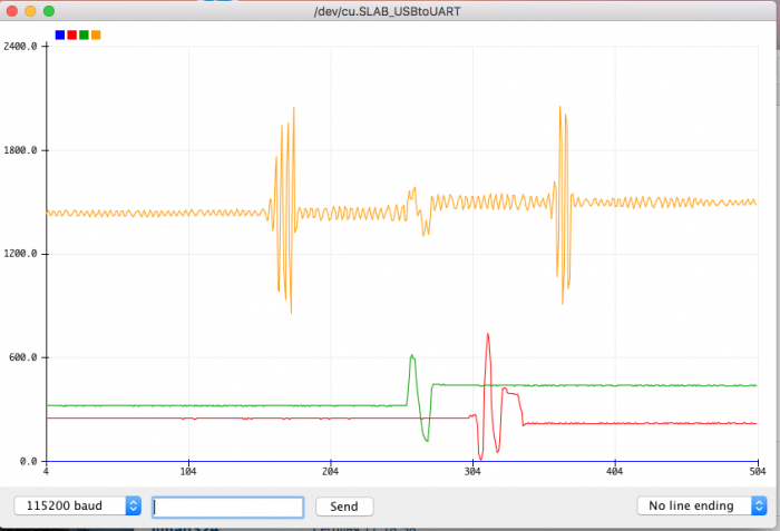
сделал sum3 потому что sum1 принадлежит для PA .
PA6 и PA7 = хорошо, PB0 = не хорошо .
PB0 регирует на любую частоту = оранцовая линия, голубая линия = 0 должна регировать на одну частоту.
#include "arduinoFFT.h"

#define SAMPLES 128             //Must be a power of 2
#define SAMPLING_FREQUENCY 40000 //Hz, must be less than 10000 due to ADC

#include <STM32ADC.h>
STM32ADC myADC(ADC1);

//uint8 pins[] = {PA6, PA7};
uint8 pins[] = {PA6, PA7, PB0};


const int maxSamples = 2;
uint16_t dataPoints[maxSamples];
//long sum1, sum2;
long sum1, sum2, sum3;
arduinoFFT FFT = arduinoFFT();

unsigned int sampling_period_us;
unsigned long microseconds;

double vReal[SAMPLES];
double vImag[SAMPLES];

void setup() {
  Serial.begin(115200);


  myADC.calibrate();
  rcc_set_prescaler(RCC_PRESCALER_ADC, RCC_ADCPRE_PCLK_DIV_8);
  pinMode(PA6, INPUT_ANALOG);
  pinMode(PA7, INPUT_ANALOG);
  pinMode(PB0, INPUT_ANALOG);
  myADC.setSampleRate(ADC_SMPR_239_5);
  myADC.setScanMode();
  // myADC.setPins(pins, 2);

  ////////////////////////
  myADC.setPins(pins, 3);
  ////////////////////////

  myADC.setContinuous();
  //myADC.setDMA(dataPoints, 2, (DMA_MINC_MODE | DMA_CIRC_MODE), NULL);
  myADC.setDMA(dataPoints, 3, (DMA_MINC_MODE | DMA_CIRC_MODE), NULL);
  myADC.startConversion();

  sampling_period_us = round(1000000 * (1.0 / SAMPLING_FREQUENCY));

}

void loop() {

  for (int j = 0; j < 10; j++) {
    sum1 = sum1 + dataPoints[0];
    sum2 = sum2 + dataPoints[1];
    sum3 = sum3 + dataPoints[2];
    delay(1);
  }

  /*SAMPLING*/

  for (int j = 0; j < SAMPLES; j++)
  {
    microseconds = micros();    //Overflows after around 70 minutes!

    //vReal[t] = analogRead(PB0);
    //. vReal[t] = sum1 / 10;
    vReal[j] = sum3 / 10;
    vImag[j] = 0;

    while (micros() < (microseconds + sampling_period_us)) {
    }
  }

  /////////////////////////////
  /*SAMPLING*/
  /*
    for (int t = 0; t < SAMPLES; t++)
    {
    microseconds = micros();    //Overflows after around 70 minutes!

    //vReal[t] = analogRead(PB0);
    //. vReal[t] = sum1 / 10;
    vReal[t] = sum3 / 10;
    vImag[t] = 0;

    while (micros() < (microseconds + sampling_period_us)) {
    }
    }
    //////////////////////////////
  */
  /*FFT*/
  FFT.Windowing(vReal, SAMPLES, FFT_WIN_TYP_HAMMING, FFT_FORWARD);
  FFT.Compute(vReal, vImag, SAMPLES, FFT_FORWARD);
  FFT.ComplexToMagnitude(vReal, vImag, SAMPLES);
  double peak = FFT.MajorPeak(vReal, SAMPLES, SAMPLING_FREQUENCY);

  Serial.print(vReal[34], 1); //orange
  Serial.print("   ");
  Serial.print(sum1 / 10); sum1 = 0;//PA6, green
  Serial.print("   ");
  Serial.print(sum2 / 10); sum2 = 0;//PA7, red
  Serial.print("   ");
  Serial.println(sum3 / 10); sum3 = 0;// blue
  //delay(100);
}Вот пытаюсь переделать fft чтобы работало с sum3, пока не получилось.
Оригинал = работает.
#include "arduinoFFT.h"
#define SAMPLES 128 //Must be a power of 2
#define SAMPLING_FREQUENCY 40000 //Hz, must be less than 10000 due to ADC
arduinoFFT FFT = arduinoFFT();
unsigned int sampling_period_us;
unsigned long microseconds;
double vReal[SAMPLES];
double vImag[SAMPLES];
void setup() {
Serial.begin(115200);
sampling_period_us = round(1000000 * (1.0 / SAMPLING_FREQUENCY));
}
void loop() {
/*SAMPLING*/
for (int t = 0; t < SAMPLES; t ++)
{
microseconds = micros(); //Overflows after around 70 minutes!
vReal[t ] = analogRead(PB0);
vImag[t ] = 0;
while (micros() < (microseconds + sampling_period_us)) {
}
}
/*FFT*/
FFT.Windowing(vReal, SAMPLES, FFT_WIN_TYP_HAMMING, FFT_FORWARD);
FFT.Compute(vReal, vImag, SAMPLES, FFT_FORWARD);
FFT.ComplexToMagnitude(vReal, vImag, SAMPLES);
double peak = FFT.MajorPeak(vReal, SAMPLES, SAMPLING_FREQUENCY);
for (int t = 10; t < (SAMPLES / 2);t++)
{
Serial.print(vReal[t ], 1);
Serial.print(" ");
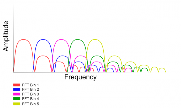
Serial.println(vReal[34], 1); //View only this line in serial plotter to visualize the bins
}
//delay(1000); //Repeat the process every second OR:
//while(1); //Run code once
}Переделка = не работает.
#include "arduinoFFT.h"

#define SAMPLES 128
#define SAMPLING_FREQUENCY 40000
arduinoFFT FFT = arduinoFFT();

///////////////////
#include <STM32ADC.h>
STM32ADC myADC(ADC1);

uint8 pins[] = {PB0};

const int maxSamples = 2;
uint16_t dataPoints[maxSamples];
long sum3;
////////////////////

unsigned int sampling_period_us;
unsigned long microseconds;

double vReal[SAMPLES];
double vImag[SAMPLES];

void setup() {
  Serial.begin(115200);
  /////////////////////////////
  myADC.calibrate();
  rcc_set_prescaler(RCC_PRESCALER_ADC, RCC_ADCPRE_PCLK_DIV_8);

  pinMode(PB0, INPUT_ANALOG);

  myADC.setSampleRate(ADC_SMPR_239_5);
  myADC.setScanMode();
  myADC.setPins(pins, 2);
  myADC.setContinuous();
  myADC.setDMA(dataPoints, 2, (DMA_MINC_MODE | DMA_CIRC_MODE), NULL);
  myADC.startConversion();
  ////////////////////////////

  sampling_period_us = round(1000000 * (1.0 / SAMPLING_FREQUENCY));
}

void loop() {

  /*SAMPLING*/
  for (int t = 0; t < SAMPLES; t++)
  {
    microseconds = micros();
  vReal[t] = sum3 / 10;
   // vReal[t] = analogRead(PB0);
    vImag[t] = 0;

    while (micros() < (microseconds + sampling_period_us)) {
    }
  }

  /*FFT*/
  FFT.Windowing(vReal, SAMPLES, FFT_WIN_TYP_HAMMING, FFT_FORWARD);
  FFT.Compute(vReal, vImag, SAMPLES, FFT_FORWARD);
  FFT.ComplexToMagnitude(vReal, vImag, SAMPLES);
  double peak = FFT.MajorPeak(vReal, SAMPLES, SAMPLING_FREQUENCY);

  ////////////////////
  for (int t = 5; t < 10; t++) {
    sum3 = sum3 + dataPoints[0];

    delay(1);
  }

  for (int t = 5; t < (SAMPLES / 2); t++)
  {
    sum3 = sum3 + dataPoints[0];

    Serial.print(sum3 / 10); sum3 = 0;
    Serial.print(" ");
    //Serial.print(vReal[t], 1);
    //Serial.print(" ");
    Serial.println(vReal[34], 1);    //View only this line in serial plotter to visualize the bins
  }

  delay(10);  //Repeat the process every second OR:

}#include "arduinoFFT.h"
#define SAMPLES 128
#define SAMPLING_FREQUENCY 40000
arduinoFFT FFT = arduinoFFT();
///////////////////
#include <STM32ADC.h>
STM32ADC myADC(ADC1);
uint8 pins[] = {PB0};
const int maxSamples = 1;
uint16_t dataPoints[maxSamples];
long sum3;
////////////////////
unsigned int sampling_period_us;
unsigned long microseconds;
double vReal[SAMPLES];
double vImag[SAMPLES];
void setup() {
Serial.begin(115200);
/////////////////////////////
myADC.calibrate();
rcc_set_prescaler(RCC_PRESCALER_ADC, RCC_ADCPRE_PCLK_DIV_8);
pinMode(PB0, INPUT_ANALOG);
myADC.setSampleRate(ADC_SMPR_239_5);
myADC.setScanMode();
myADC.setPins(pins, 1);
myADC.setContinuous();
myADC.setDMA(dataPoints, 1, (DMA_MINC_MODE | DMA_CIRC_MODE), NULL);
myADC.startConversion();
////////////////////////////
sampling_period_us = round(1000000 * (1.0 / SAMPLING_FREQUENCY));
}
void loop() {
/*SAMPLING*/
for (int t = 0; t < SAMPLES; t++)
{
microseconds = micros();
vReal[t] = dataPoints[0];
vImag[t] = 0;
while (micros() < (microseconds + sampling_period_us)) {
}
}
/*FFT*/
FFT.Windowing(vReal, SAMPLES, FFT_WIN_TYP_HAMMING, FFT_FORWARD);
FFT.Compute(vReal, vImag, SAMPLES, FFT_FORWARD);
FFT.ComplexToMagnitude(vReal, vImag, SAMPLES);
double peak = FFT.MajorPeak(vReal, SAMPLES, SAMPLING_FREQUENCY);
for (int t = 5; t < (SAMPLES / 1); t++)
{
Serial.println(vReal[34], 1); //View only this line in serial plotter to visualize the bins
}
/// delay(10); //Repeat the process every second OR:
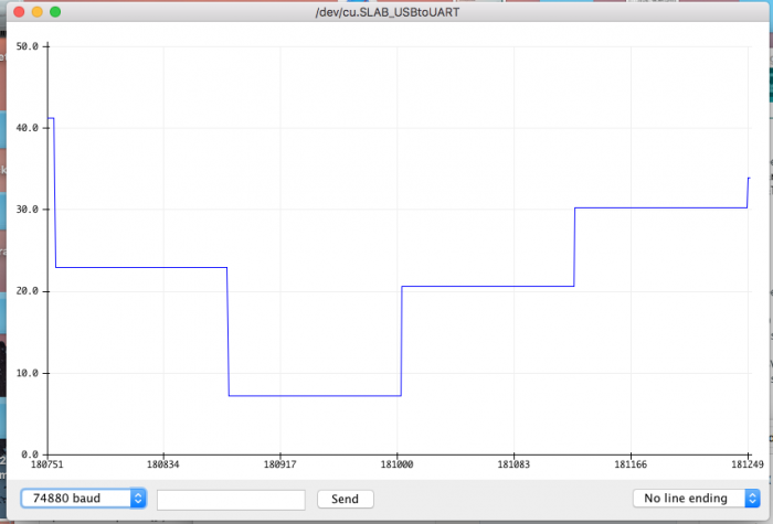
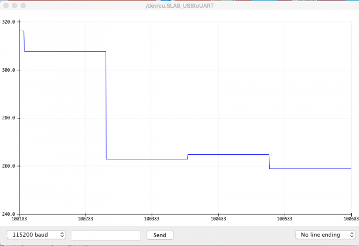
}Получилось так, без сигнала номера прыгают от 8 до 42, с сигналом 280 до 320. Надо добавить усреднение = sum ?
Почему то на LCD два нуля ?
На сериал монитор 28 и 30 а на LCD 0 и 0.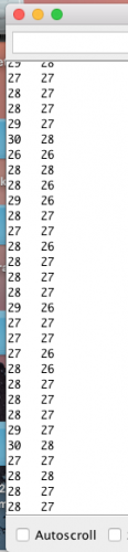
#include <LiquidCrystal.h>
LiquidCrystal lcd(PA0, PA1, PA2, PA3, PA4, PA5);
#include <STM32ADC.h>

STM32ADC myADC(ADC1);

uint8 pins[] = {PA6, PA7};

const int maxSamples = 2;
uint16_t dataPoints[maxSamples];
long sum1, sum2;

void setup() {
  Serial.begin(115200);
  lcd.begin(16, 2);
  myADC.calibrate();
  rcc_set_prescaler(RCC_PRESCALER_ADC, RCC_ADCPRE_PCLK_DIV_8);
  pinMode(PA6, INPUT_ANALOG);
  pinMode(PA7, INPUT_ANALOG);

  myADC.setSampleRate(ADC_SMPR_239_5);
  myADC.setScanMode();
  myADC.setPins(pins, 2);
  myADC.setContinuous();
  myADC.setDMA(dataPoints, 2, (DMA_MINC_MODE | DMA_CIRC_MODE), NULL);
  myADC.startConversion();
}

void loop() {
  for (int j = 0; j < 10; j++) {
    sum1 = sum1 + dataPoints[0];
    sum2 = sum2 + dataPoints[1];
    delay(1);
  }

  Serial.print(sum1 / 10); sum1 = 0;
  Serial.print("   ");
  Serial.println(sum2 / 10); sum2 = 0;

  lcd.setCursor(0, 0);
  lcd.print(sum1 / 10); sum1 = 0;

  lcd.setCursor(0, 1);
  lcd.print(sum2 / 10); sum2 = 0;

}Serial.print(sum1 / 10); //sum1 = 0;
Serial.print(" ");
Serial.println(sum2 / 10); //sum2 = 0;
lcd.setCursor(0, 0);
lcd.print(sum1 / 10); sum1 = 0;
lcd.setCursor(0, 1);
lcd.print(sum2 / 10); sum2 = 0;
Большое спасибо
В первых двух колонках почему то после запятой одни нуля ?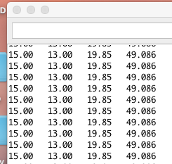
float  UxValue = 0;
float  UxValue2 ;
/*
int  UxValue = 0;
int  UxValue2 = 0;
*/
#include <LCD5110_Graph.h>
//LCD5110 lcd(PA4, PA3, PA2, PA0, PA1);
LCD5110 lcd(PA0, PA1, PA2, PA4, PA3);
extern unsigned char SmallFont[];char UxString [6];
char UxString2 [6];
char MString3 [6];
char EString4 [6];String str;
String str2;
String str3;
String str4;//////////////////////////////////////////////////////////////////////////////////
float UxValue = 0;
float UxValue2 ;
/*
int UxValue = 0;
int UxValue2 = 0;
*/
///////////////////////////////////////////////////////////////////////////////int M = 0;
int E = 0;
#include <STM32ADC.h>STM32ADC myADC(ADC1);
uint8 pins[] = {PA6, PA7};
const int maxSamples = 2;
uint16_t dataPoints[maxSamples];
long sum1, sum2;void setup() {
lcd.InitLCD();
lcd.setFont(SmallFont);Serial.begin(115200);
myADC.calibrate();
rcc_set_prescaler(RCC_PRESCALER_ADC, RCC_ADCPRE_PCLK_DIV_8);
pinMode(PA6, INPUT_ANALOG);
pinMode(PA7, INPUT_ANALOG);myADC.setSampleRate(ADC_SMPR_239_5);
myADC.setScanMode();
myADC.setPins(pins, 2);
myADC.setContinuous();
myADC.setDMA(dataPoints, 2, (DMA_MINC_MODE | DMA_CIRC_MODE), NULL);
myADC.startConversion();
}void loop() {
lcd.clrScr();
lcd.update();
float M = sqrt(UxValue * UxValue + UxValue2 * UxValue2);
float E = (float) RAD_TO_DEG * (atan2(UxValue, UxValue2));UxValue = sum1 / 10; sum1 = 0;// UxValue = analogRead(PA6);
UxValue2 = sum2 / 10; sum2 = 0;// UxValue2 = analogRead(PA7);UxValue = map( UxValue, 0, 4095, 0, 65);
UxValue2 = map( UxValue2, 0, 4095, 0, 65);
//M = map( M, 0, 4095, 0, 94);
str = String(UxValue) ;
str2 = String(UxValue2) ;
str3 = String(M) + "°";
str4 = String(E) + "%";
str.toCharArray(UxString, 6);
str2.toCharArray(UxString2, 6);
str3.toCharArray(MString3, 6);
str4.toCharArray(EString4, 6);fillBar( UxValue); //displays line
lcd.print(UxString, 2, 0); // displays # in %, position x, y
fillBar2( UxValue2); //displays line
lcd.print(UxString2, 22, 0); // displays # in %, position x, y
fillBar3( M);
lcd.print(MString3, 46, 0); // magnitude in #
fillBar4( E);
lcd.print(EString4, 46, 10);lcd.update();
for (int j = 0; j < 10; j++) {
sum1 = sum1 + dataPoints[0];
sum2 = sum2 + dataPoints[1];
delay(1);
}Serial.print(UxValue);
Serial.print(" ");
Serial.print(UxValue2);
Serial.print(" ");
Serial.print(M);
Serial.print(" ");
Serial.println(E, 3); // = x/y}
void fillBar(int percent)
{
percent = map(percent, 0, 100, 0, 90);
lcd.drawLine(2, 42, percent, 42);//x, y}
void fillBar2(int percent2)
{
percent2 = map(percent2, 0, 100, 0, 90);
lcd.drawLine(2, 46, percent2, 46); //x, y
}void fillBar3(int percent3)
{
percent3 = map(percent3, 0, 100, 0, 90);//magnitude bar
lcd.drawLine(2, 44, percent3, 44); //x, y
}
void fillBar4(int percent4)
{
percent4 = map(percent4, 0, 100, 0, 90);//magnitude bar
lcd.drawLine(2, 20, percent4, 20); //x, y
}
UxValue = sum1 / 10; sum1 = 0;// UxValue = analogRead(PA6);
UxValue2 = sum2 / 10; sum2 = 0;// UxValue2 = analogRead(PA7);
UxValue = sum1 / 10.00; sum1 = 0;// UxValue = analogRead(PA6);
UxValue2 = sum2 / 10.00; sum2 = 0;// UxValue2 = analogRead(PA7);
ничего не изменилось
float  M = sqrt(UxValue * UxValue + UxValue2 * UxValue2);
  float E = (float) RAD_TO_DEG * (atan2(UxValue, UxValue2));

  // UxValue = sum1 / 10; sum1 = 0;// UxValue = analogRead(PA6);
  // UxValue2 = sum2 / 10; sum2 = 0;// UxValue2 = analogRead(PA7);

  UxValue = sum1 / 10.00; sum1 = 0;// UxValue = analogRead(PA6);
UxValue2 = sum2 / 10.00; sum2 = 0;// UxValue2 = analogRead(PA7)UxValue и UxValue2 это данные измерения входов PА6 PА7, а это int, только целое число.
int было в начале, пробовал float но не получилось.
float UxValue = 0;
float UxValue2 ;
/*
int UxValue = 0;
int UxValue2 = 0;
*/
Чтобы отправить ответ, вы должны войти или зарегистрироваться
forum.rcl-radio.ru → Тестирование скетчей → Измерение напряжения STM32 (Arduino IDE)
Форум работает на PunBB, при поддержке Informer Technologies, Inc
|
|