/*
* File: newmain.c
* Author: User
*
* Created on 19 ?????? 2024 ?., 14:20
*/
#include <htc.h>
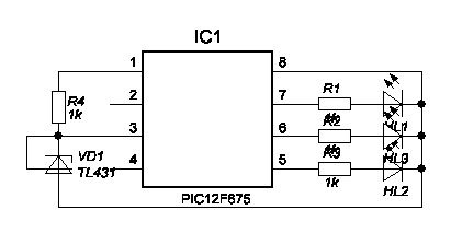
#pragma config WDTE=OFF, MCLRE=OFF, BOREN=OFF, FOSC=INTRCIO, CP=OFF, CPD=OFF //,INTRCIO
#define _XTAL_FREQ 4000000
#define LCD_DC GP0
#define LCD_RST GP1
#define LCD_DAT GP4
#define LCD_CLK GP5
#define sr GPIO2 //sensor pin2
#define sr_in TRISIO2=1 //sensor is input
#define sr_out TRISIO2=0 //sensor is output
void writecommand(int command); //
void writedata(int data);
void cursorxy (unsigned short x,unsigned short y);
void clearram(void);
void initlcd(void);
void lcdPrintChar( unsigned short row, unsigned short col,unsigned short ch);
extern const uint8_t SMALL_FONT[];
const uint8_t SMALL_FONT[] = {
0x00,0xF0,0xFC,0xFE,0x06,0x02,0x06,0xFE,0xFC,0xF0,0x00, // 0
0x00,0x07,0x1F,0x3F,0x30,0x20,0x30,0x3F,0x1F,0x07,0x00,
0x00,0x00,0x08,0x0C,0xFC,0xFE,0xFE,0x00,0x00,0x00,0x00, // 1
0x00,0x20,0x20,0x20,0x3F,0x3F,0x3F,0x20,0x20,0x20,0x00,
0x00,0x0C,0x0E,0x06,0x02,0x02,0x86,0xFE,0x7C,0x38,0x00, // 2
0x00,0x30,0x38,0x3C,0x36,0x33,0x31,0x30,0x30,0x38,0x00,
0x00,0x0C,0x0E,0x86,0x82,0x82,0xC6,0xFE,0x7C,0x38,0x00, // 3
0x00,0x18,0x38,0x30,0x20,0x20,0x31,0x3F,0x1F,0x0E,0x00,
0x00,0x00,0xC0,0x20,0x18,0x04,0xFE,0xFE,0xFE,0x00,0x00, // 4
0x00,0x03,0x02,0x02,0x02,0x22,0x3F,0x3F,0x3F,0x22,0x02,
0x00,0x00,0x7E,0x7E,0x46,0x46,0xC6,0xC6,0x86,0x00,0x00, // 5
0x00,0x18,0x38,0x30,0x20,0x20,0x30,0x3F,0x1F,0x0F,0x00,
0x00,0xC0,0xF0,0xF8,0xFC,0x4C,0xC6,0xC2,0x82,0x00,0x00, // 6
0x00,0x0F,0x1F,0x3F,0x30,0x20,0x30,0x3F,0x1F,0x0F,0x00,
0x00,0x06,0x06,0x06,0x06,0x06,0xC6,0xF6,0x3E,0x0E,0x00, // 7
0x00,0x00,0x00,0x30,0x3C,0x0F,0x03,0x00,0x00,0x00,0x00,
0x00,0x38,0x7C,0xFE,0xC6,0x82,0xC6,0xFE,0x7C,0x38,0x00, // 8
0x00,0x0E,0x1F,0x3F,0x31,0x20,0x31,0x3F,0x1F,0x0E,0x00,
0x00,0x78,0xFC,0xFE,0x86,0x02,0x86,0xFE,0xFC,0xF8,0x00, // 9
0x00,0x00,0x00,0x21,0x21,0x31,0x1D,0x1F,0x0F,0x03,0x00,
0xF0,0xF8,0x0C,0x06,0x02,0x02,0x02,0x02,0x0E,0x0C,0x00, // C
0x03,0x07,0x0C,0x18,0x10,0x10,0x10,0x10,0x1C,0x0C,0x00,
0x00,0x06,0x06,0x09,0x09,0x09,0x09,0x06,0x06,0x00,0x00, // degrees
0x00,0x00,0x00,0x00,0x00,0x00,0x00,0x00,0x00,0x00,0x00,
0x00,0x80,0x80,0x80,0x80,0x80,0x80,0x80,0x80,0x80,0x00, // minus sign
0x00,0x01,0x01,0x01,0x01,0x01,0x01,0x01,0x01,0x01,0x00
};
unsigned char i;
void main()
{
GPIO = 0;
TRISIO = 0b001100; //
ANSEL = 0x00; // Set ports as digital I/O, not analog input
ADCON0 = 0x00; // Shut off the A/D Converter
CMCON = 0x07; // Shut off the Comparator
VRCON = 0x00; // Shut off the Voltage Reference
initlcd();
clearram();
//read sensor
// cursorxy (0,3); // set the cursor to position x=3 and y-3
//writedata(255); // write a solid byte of all 8 bits
while(1){
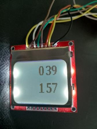
lcdPrintChar(0, 40,0);
// lcdPrintChar(3, 47,d[1]);
lcdPrintChar(0, 53,3);
// lcdPrintChar(3, 56,d[2]);
lcdPrintChar(0, 63, 9);
// lcdPrintChar(3, 70, 11);
lcdPrintChar(3, 40,1);
// lcdPrintChar(3, 47,d[1]);
lcdPrintChar(3, 53,5);
// lcdPrintChar(3, 56,d[2]);
lcdPrintChar(3, 63, 7);
// lcdPrintChar(3, 70, 11);
__delay_ms(1000);
}
}
void writecommand(int command)
{
LCD_DC=0; // byte is a command it is read with the eight SCLK pulse
for (unsigned short t=8;t>0;t--)
{
LCD_CLK=0;
if ((command&0x80)==0)
{
LCD_DAT=0;
}
else
{
LCD_DAT=1;
}
LCD_CLK=1;
command=command<<1;
}
}
void writedata(int data)
{
LCD_DC=1;
for (unsigned short t=8;t>0;t--)
{
LCD_CLK=0;
if ((data&0x80)==0)
{
LCD_DAT=0;
}
else
{
LCD_DAT=1;
}
LCD_CLK=1;
data=data<<1;
}
}
void cursorxy (unsigned short x, unsigned short y) // Nokia LCD Position cursor
{
writecommand(0x40|(y&0x07));
writecommand(0x80|(x&0x7f));
}
void clearram(void)
{
unsigned int lcdram;
cursorxy(0,0);
for (lcdram=504;lcdram>0;lcdram--)
writedata(0); // write all 504 LCDRAM addresses.
}
void initlcd(void)
{
LCD_RST=0; // reset LCD
__delay_ms(100); // Wait 100ms
LCD_RST=1;// release from reset
writecommand(0x21); // Activate Chip and H=1.
writecommand(0xC2); // Set LCD Voltage to about 7V.
writecommand(0x13); // Adjust voltage bias.
writecommand(0x20); // Horizontal addressing and H=0.
writecommand(0x09); // Activate all segments.
clearram(); // Erase all pixel on the lcdram.
writecommand(0x08); // Blank the Display.
writecommand(0x0C); // Display Normal.
cursorxy(0,0); // Cursor Home.
}
void lcdPrintChar( unsigned short row, unsigned short col,unsigned short ch){
//const unsigned char *chdata = SMALL_FONT + (ch * 22);
cursorxy (col,row);
for(unsigned char i = 0; i < 11; i++) {
writedata(SMALL_FONT[(ch*22+i)]);}
cursorxy (col,row+1);
for(unsigned char i = 11; i < 22; i++) {
writedata(SMALL_FONT[(ch*22+i)]);}
writedata(0x00);
}