1

Тема: Проекты в программе Flowcode

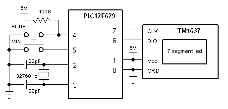
Простые часы Pic12f629 & tm1637
http://forum.rcl-radio.ru/uploads/images/2023/12/66ed2c34922f56436317e9fad8323829.bmp
Прошивка и файл проекта
Данный контент доступен только зарегистрированным пользователям.
Часы первичные для механических часов "Стрела". Pic12f675(629)
http://forum.rcl-radio.ru/uploads/images/2023/12/f10faa57fbae2ff5a9b6355a99b904b2.jpg
Прошивка и файл проекта
Данный контент доступен только зарегистрированным пользователям.

2 (2024-04-24 14:57:31 отредактировано klause)

Re: Проекты в программе Flowcode

Простые часы в другой программе MPLAB IDE. Схема такая же.
Данный контент доступен только зарегистрированным пользователям.
Второй вариант с DS3231.
Данный контент доступен только зарегистрированным пользователям.
Третий вариант с DS1307.
Данный контент доступен только зарегистрированным пользователям.
Интересно, что в  DS1307 7бит в регистре секунд установить в ноль надо.

3

Re: Проекты в программе Flowcode

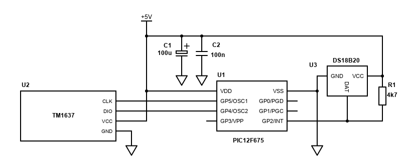
Термометр DS18b20.
http://forum.rcl-radio.ru/uploads/images/2024/04/87d75190965e05fa74522edb69ae2198.png
Проект в  программе MPLAB IDE
Данный контент доступен только зарегистрированным пользователям.

4 (2024-05-18 12:58:43 отредактировано klause)

Re: Проекты в программе Flowcode

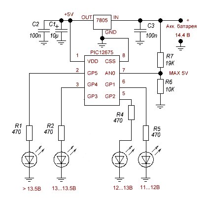
Схемка из основного сайта.
http://forum.rcl-radio.ru/uploads/images/2024/04/025e07361743279463041458ec6576a1.jpg

/*
 * File:   newmain.c
 * Author: User
 *
 * Created on 19 ?????? 2024 ?., 14:20
 */
#include <htc.h>
#pragma config WDTE=OFF, MCLRE=OFF, BOREN=OFF, FOSC=INTRCIO, CP=OFF, CPD=OFF    //,INTRCIO
#define _XTAL_FREQ 4000000

void main(void){
	 unsigned int count;
    	// PIC I/O init
    CMCON = 0b111;		//comparator off
    GPIO = 0b00110110;
    TRISIO = 0b00000001;   //GP0 input
    ANSEL = 0b01010001;   //Fosc/16, AN0 pin7
	ADCON0 = 0b10000001;	//right justified, AN0, ADC on 
    
	while(1) {
        GO_DONE = 1;				//start ADC
        while(GO_DONE){};
        
        count=((ADRESH << 8) + ADRESL);
        if(count>=1016){GPIO = 0b00100000;
        __delay_ms(500);
        GPIO = 0b00000000;}
        if((count<1016)&&(count>=952)){GPIO = 0b00100000;}
        if((count<952)&&(count>=918)){GPIO = 0b00010000;}
        if((count<918)&&(count>=846)){GPIO = 0b00000100;}
        if((count<846)&&(count>=776)){GPIO = 0b00000010;}
        if((count<776)&&(count>600)){
           GPIO = 0b00000010;
        __delay_ms(500);
        GPIO = 0b00000000;
        }
        if(count<600){
         GPIO = 0b00110110;
          __delay_ms(500);
        GPIO = 0b00000000;
        }
        __delay_ms(500);
	}
	
}

Файлы проекта.
Данный контент доступен только зарегистрированным пользователям.

5 (2024-05-15 12:39:51 отредактировано klause)

Re: Проекты в программе Flowcode

Датчик влажности и температуры DHT11 + pic12f675+TM1637

/*
 * File:   newmain.c
 * Author: User
 *
 * Created on 19 ?????? 2024 ?., 14:20
 */

#include <htc.h>

#pragma config WDTE=OFF, MCLRE=OFF, FOSC=INTRCIO, CP=OFF

#define _XTAL_FREQ 4000000
#define DIO GPIO4 //pin3
#define CLK GPIO5 //pin2
#define DIOio TRISIO4 // input or output 
#define Data GPIO2		//sensor  pin5
#define DataDir TRISIO2		//sensor input or output

//prototypes
void display( unsigned char addr, unsigned char fig );
void sendData(unsigned char dataB);
void startBit(void);
void stopBit(void);
void clock(void);
void dht11_init(void);
unsigned short find_response();
unsigned short read_dht11();
unsigned int counter = 0, TempC, RH;
unsigned short T_Byte1, T_Byte2, RH_Byte1, RH_Byte2;
const unsigned char  num[] = {0x3f,0x06,0x5b,0x4f,0x66,0x6d,0x7d,0x07,0x7f,0x6f}; //0,1,2,3...9
unsigned short TOUT = 0,CheckSum, i, check;
void main(void){
    unsigned char i;
    GPIO = 0b00000000; 
    TRISIO = 0b00001100; //  
    ANSEL = 0; // 
    CMCON = 7; //
    OPTION_REG = 0;	//pullup
    CLK=1;
    DIO=1;
 GIE = 1;    //Enable global interrupt
 PEIE = 1;   //Enable peripheral interrupt
  // Configure Timer2 module
 TMR1IE = 1;  // Enable Timer1 interrupt
   T1CON = 0;       // Prescaler 1:1, and Timer1 is off initially
 TMR1IF =0;   // Clear TMR INT Flag bit
  TMR1H = 0;
  TMR1L = 0; 
    
	do{
  
        dht11_init();
        check = find_response();
        if (!check) {
           RH = 0;
           TempC = 0;
        }
        else{
             RH_Byte1 = read_dht11();
             RH_Byte2 = read_dht11();
             T_Byte1 = read_dht11();
             T_Byte2 = read_dht11();
             CheckSum = read_dht11();
             // Check for error in Data reception
             if (CheckSum == ((RH_Byte1 + RH_Byte2 + T_Byte1 + T_Byte2) & 0xFF))
             {
               TempC = T_Byte1;
               RH = RH_Byte1;
              
              }
              else{
                   TempC = 0;
                   RH = 0;
              }
        }
        __delay_ms(2000);
    
            display(0,0b01110110);
            display(1,0b00011100);
            display(2,num[( RH/ 10)%10]);
            display(3,num[( RH/ 10)%10]);
         __delay_ms(2000); 
         
          display(0,num[( TempC / 10) % 10]);
          display(1,num[  TempC % 10]);
          display(2,0b01100011);
          display(3,0b00111001);
    
  }while(1);
}


void sendData(unsigned char dataB)
{
    for(unsigned char b=0;b<8;b++){
       DIO=(dataB >> b) % 2;
       clock();
    }
    DIOio=1;   //make DIO input
    clock();
    __delay_us(5);
    DIOio=0;   //make DIO output

}

void clock(void)
{
   __delay_us(4);
   CLK=1;
   __delay_us(5);
   CLK=0;
   __delay_us(4);
}

void startBit(void)
{
    DIO=0;
    __delay_us(5);
    CLK=0;
}

void stopBit(void)
{
    CLK=1;
    __delay_us(5);
    DIO=1;
}

    //includes brightness and point setting.
void display( unsigned char addr, unsigned char fig ){
    unsigned char mode=0b01000100;// control=0b10001100;  //0b10001010
    unsigned char brightness=7; //brightness can be selected 0 to 7
    unsigned char control=136+brightness;
   // fig=fig+0x80;    //0x80 is point 
    addr +=192;
    startBit();
    sendData(mode);            // command1-data 
    stopBit();
    startBit();
    sendData(addr);            // command2-address
    sendData(fig);
    stopBit();
    startBit();
    sendData(control);             // command3-control
    stopBit();
}
void dht11_init(){
  DataDir = 0;     // Data port is output
  Data    = 0;
  __delay_ms(25);
  Data    = 1;
  __delay_us(30);
  DataDir = 1;     // Data port is input

 }

 unsigned short find_response(){
 TOUT = 0;
  TMR1L = 0;
  TMR1H = 0;
  TMR1ON = 1;      // start timer
  while(!Data && !TOUT);
  if (TOUT) return 0;
  else {
   TMR1L = 0;
   TMR1H = 0;
   while(Data && !TOUT);
   if (TOUT) return 0;
   else {
   TMR1ON = 0;
    return 1;
   }
  }
 }
 
unsigned short read_dht11(){
  unsigned short num = 0;
  DataDir = 1;
  for (i=0; i<8; i++){
   while(!Data);
   TMR1L = 0;
   TMR1H = 0;
   TMR1ON = 1;
   while(Data);
   TMR1ON = 0;
   if(TMR1L > 40) num |= 1<<(7-i);  // If time > 40us, Data is 1
  }
  return num;
 }
void __interrupt() ISR(void){
  if(TMR1IF){
   TOUT = 1;
   TMR1ON = 0; // stop timer
   TMR1IF  = 0; // Clear TMR1 interrupt flag
  }
}

Данный контент доступен только зарегистрированным пользователям.

6

Re: Проекты в программе Flowcode

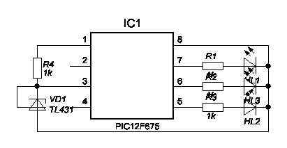
Индикатор литиевого аккумулятора. Размышления в теории. > 4.2в мигает зеленый светодиод. 4,2 - 3,8в горит зеленый  светодиод.3,8-3,4в горит желтый светодиод.3,4-3в горит красный  светодиод.<3в мигает красный светодиод. Обычно измеряют напряжение с помощью опорного напряжения. АЦП результат = Uвх*1024/Uref. Думаю, если сделать так, чтобы не делать делитель напряжения. Uвх будет опорным напряжением, например 2.5(1.5)в через TL431(432). А Uref будет настроен на U питания. Главное, чтобы U питания был не меньше 2.5в. Хотя защита литиевого аккумулятора сработает при напряжении 2.5в.
http://forum.rcl-radio.ru/uploads/images/2024/05/0c50cab583648c0bbc825f5c433e139b.bmp

/*
 * File:   newmain.c
 * Author: User
 *
 * Created on 19 ?????? 2024 ?., 14:20
 */
#include <htc.h>
#pragma config WDTE=OFF, MCLRE=OFF, BOREN=OFF, FOSC=INTRCIO, CP=OFF, CPD=OFF    //,INTRCIO
#define _XTAL_FREQ 4000000

void main(void){
	 unsigned int count;
    	// PIC I/O init
    CMCON = 0b111;		//comparator off
    GPIO = 0;
    TRISIO = 0b00011000;   //GPIO4 input
    ANSEL = 0b01011000;   //Fosc/16, AN3 pin3
	ADCON0 = 0b10001101;	//right justified, AN3, ADC on 
    
	while(1) {
        GO_DONE = 1;				//start ADC
        while(GO_DONE){};
        
        count=((ADRESH << 8) + ADRESL);
        if((count>601)&&(count<609)){GPIO = 0b00000001;//blue
         __delay_ms(500);
        GPIO=0;} 
        if((count>609)&&(count<673)){GPIO = 0b0000001;}//blue
        if((count>673)&&(count<752)){GPIO = 0b0000010;}//green
        if((count>752)&&(count<852)){GPIO = 0b0000100;}//red
        if((count>852)&&(count<1024)){GPIO = 0b00000100;//red
        __delay_ms(500);
        GPIO=0;
        }           
        __delay_ms(500);
	}
	
}

Данный контент доступен только зарегистрированным пользователям.

7 (2024-06-12 12:11:15 отредактировано klause)

Re: Проекты в программе Flowcode

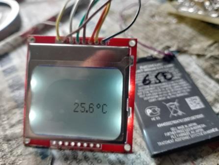
Термометр
Pc12f675&lcdnokia3310&DS18b20

/*
 * File:   newmain.c
 * Author: User
 *
 * Created on 19 ?????? 2024 ?., 14:20
 */
#include <htc.h>
#pragma config WDTE=OFF, MCLRE=OFF, BOREN=OFF, FOSC=INTRCIO, CP=OFF, CPD=OFF    //,INTRCIO
#define _XTAL_FREQ 4000000

#define LCD_DC  GP0		
#define LCD_RST GP1
#define LCD_DAT GP4
#define LCD_CLK GP5
#define sr GPIO2		//sensor  pin2
#define sr_in TRISIO2=1		//sensor is input
#define sr_out TRISIO2=0		//sensor is output
unsigned char sensor_rst(void);
unsigned char reply (void);
void cmnd_w(unsigned char cmnd);
void writecommand(int command);  // 
void writedata(int data);
void cursorxy (unsigned short x,unsigned short  y);
void clearram(void);
void initlcd(void);
void lcdPrintChar( unsigned short row, unsigned short col,unsigned short ch);

extern const uint8_t SMALL_FONT[];
const uint8_t SMALL_FONT[] = {
  0x7E, 0x81, 0x81, 0x81, 0x7E, // 30 0
  0x04, 0x82, 0xFF, 0x80, 0x00, // 31 1
  0xC2, 0xA1, 0x91, 0x89, 0x86, // 32 2
  0x42, 0x81, 0x89, 0x89, 0x76, // 33 3
  0x18, 0x14, 0x12, 0xFF, 0x10, // 34 4
  0x47, 0x89, 0x89, 0x89, 0x71, // 35 5
  0x7E, 0x89, 0x89, 0x89, 0x72, // 36 6
  0x01, 0xF1, 0x09, 0x05, 0x03, // 37 7
  0x76, 0x89, 0x89, 0x89, 0x76, // 38 8
  0x4E, 0x91, 0x91, 0x91, 0x7E, // 39 9
  0x08, 0x08, 0x08, 0x08, 0x08,  // 2d -
  0x7E, 0x81, 0x81, 0x81, 0x42,//c
  0x00, 0x06, 0x09, 0x09, 0x06,//gradus
  0xC0, 0xC0, 0x00, 0x00, 0x00,
  0x00, 0x00, 0x00, 0x00, 0x00,// 
  };

void main()
 {
 unsigned int temp;
unsigned char d[3], minus, tempL, tempH;//
 GPIO = 0; 
  TRISIO = 0b001100; // 
    ANSEL  = 0x00;       		// Set ports as digital I/O, not analog input
	ADCON0 = 0x00;		 		// Shut off the A/D Converter
	CMCON  = 0x07;		 		// Shut off the Comparator
	VRCON  = 0x00;	    		// Shut off the Voltage Reference

 initlcd();
 clearram();
         //read sensor
        
          
// cursorxy (0,3);	// set the cursor to position x=3 and y-3
 //writedata(255);	// write a solid byte of all 8 bits
 
 while(1){
 
        sensor_rst();	//sensor init
        cmnd_w(0xCC);	//skip ROM command
        cmnd_w(0xBE);	//read pad command
        tempL=reply();	//LSB of temp
        tempH=reply();	//MSB of temp
        sensor_rst();
        sensor_rst();
        cmnd_w(0xCC);	//skip ROM command
        cmnd_w(0x44);	//start conversion command

        //tempH=0xff; tempL=0x5e;    //-10.125

        temp = tempL | ((unsigned int)tempH << 8);	//calculate temp 
        if(temp>0x7FF){temp= ~temp+1; minus=1;}else{minus=0;}	//detect negative temp
        d[2]=((temp & 15)*10)/16;		//multiply by 10 after decimal point 
        temp=temp/16;	//remove reading beyond decimal point

        d[0]=(temp/10) %10; 	//digit on left
        d[1]=temp %10;

        if(minus){lcdPrintChar(3,36,10);}else{lcdPrintChar(3,36,14);}
        
// This is where the code goes to do stuff!
// here is a simple example
              // lcdPrintChar(1, 8, 11);
              // lcdPrintChar(1, 15,12);
              // lcdPrintChar(1, 22,13);
              // lcdPrintChar(1, 29,14);
              // lcdPrintChar(1, 36,12);
              // lcdPrintChar(1, 43,15);
              // lcdPrintChar(1, 50,17);
             //  lcdPrintChar(1, 57,11);
             //  lcdPrintChar(1, 64,16);
             //  lcdPrintChar(1, 71,15);
             //  lcdPrintChar(1, 78,17);
              lcdPrintChar(3, 40,d[0]);
              lcdPrintChar(3, 47,d[1]);
              lcdPrintChar(3, 53,13);
              lcdPrintChar(3, 56,d[2]);
              lcdPrintChar(3, 63, 12);
              lcdPrintChar(3, 70, 11);


 }
 }

void writecommand(int command)
{
LCD_DC=0;                          // byte is a command it is read with the eight SCLK pulse
for (unsigned short t=8;t>0;t--)
   {
   LCD_CLK=0;
   if ((command&0x80)==0)
      {
      LCD_DAT=0;
      }
   else
      {
      LCD_DAT=1;
      }
   LCD_CLK=1;
   command=command<<1;
   }
}

void writedata(int data)
{
LCD_DC=1;
for (unsigned short t=8;t>0;t--)
   {
   LCD_CLK=0;
   if ((data&0x80)==0)
      {
      LCD_DAT=0;
      }
   else
      {
      LCD_DAT=1;
      }
   LCD_CLK=1;
   data=data<<1;
   }
}

void cursorxy (unsigned short x, unsigned short y)          // Nokia LCD Position cursor
{
writecommand(0x40|(y&0x07));
writecommand(0x80|(x&0x7f));
}

void clearram(void)
 {
 unsigned int lcdram;

 cursorxy(0,0);
 for (lcdram=504;lcdram>0;lcdram--)
   writedata(0);                          // write all 504 LCDRAM addresses.
 }

void initlcd(void)
 {
 LCD_RST=0; // reset LCD
 __delay_ms(100);        // Wait 100ms
 LCD_RST=1;// release from reset

 writecommand(0x21);		// Activate Chip and H=1.
 writecommand(0xC2);		// Set LCD Voltage to about 7V.
 writecommand(0x13);		// Adjust voltage bias.
 writecommand(0x20);		// Horizontal addressing and H=0.
 writecommand(0x09);		// Activate all segments.
 clearram();			   // Erase all pixel on the lcdram.
 writecommand(0x08);		// Blank the Display.
 writecommand(0x0C);		// Display Normal.
 cursorxy(0,0);		   // Cursor Home.
 }
void lcdPrintChar( unsigned short row, unsigned short col,unsigned short ch){

  writecommand(0x80|(col&0x7f));
  writecommand(0x40|(row&0x07) );
   for(unsigned short i = 0; i < 5; i++) {
     writedata(SMALL_FONT[(ch*5+i)]);	// write a solid byte of all 8 bits
    };
 writedata(0x00);  
}
unsigned char reply (){	//reply from sensor
	unsigned char ret=0,i;
	
        for(i=0;i<8;i++){	//read 8 bits
            sr_out; sr=0; __delay_us(2); sr_in; __delay_us(6);
            if(sr){ret += 1 << i;} __delay_us(80);	//output high=bit is high
        }
	sr_in;
    
	return ret;
}

void cmnd_w(unsigned char cmnd){	//send command temperature sensor
	unsigned char i;
	
        for(i=0;i<8;i++){	//8 bits 
            if(cmnd & (1 << i)){sr_out; sr=0; __delay_us(2); sr_in; __delay_us(80);}
            else{sr_out; sr=0; __delay_us(80); sr_in; __delay_us(2);}	//hold output low if bit is low 
        }
        sr_in;
       
    }    


unsigned char sensor_rst(){		//reset the temperature
	
    
        sr_out;
        sr=0; __delay_us(600);
        sr_in; __delay_us(100);
        __delay_us(600);
        return sr;	//return 0 for sensor present
	
}

http://forum.rcl-radio.ru/uploads/images/2024/06/17f677bc95026f9bf9247cd8d94e7dcd.jpg

8

Re: Проекты в программе Flowcode

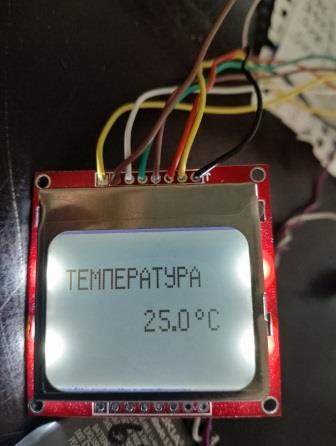
Термометр
Pc12f675&lcdnokia3310&DS18b20 Вариант 2

/*
 * File:   newmain.c
 * Author: User
 *
 * Created on 19 ?????? 2024 ?., 14:20
 */
#include <htc.h>
#pragma config WDTE=OFF, MCLRE=OFF, BOREN=OFF, FOSC=INTRCIO, CP=OFF, CPD=OFF    //,INTRCIO
#define _XTAL_FREQ 4000000

#define LCD_DC  GP0		
#define LCD_RST GP1
#define LCD_DAT GP4
#define LCD_CLK GP5
#define sr GPIO2		//sensor  pin2
#define sr_in TRISIO2=1		//sensor is input
#define sr_out TRISIO2=0		//sensor is output
unsigned char sensor_rst(void);
unsigned char reply (void);
void cmnd_w(unsigned char cmnd);
void writecommand(int command);  // 
void writedata(int data);
void cursorxy (unsigned short x,unsigned short  y);
void clearram(void);
void initlcd(void);
void lcdPrintChar( unsigned short row, unsigned short col,unsigned short ch);

extern const uint8_t SMALL_FONT[];
const uint8_t SMALL_FONT[] = {
  0x7E, 0x81, 0x81, 0x81, 0x7E, // 30 0
  0x04, 0x82, 0xFF, 0x80, 0x00, // 31 1
  0xC2, 0xA1, 0x91, 0x89, 0x86, // 32 2
  0x42, 0x81, 0x89, 0x89, 0x76, // 33 3
  0x18, 0x14, 0x12, 0xFF, 0x10, // 34 4
  0x47, 0x89, 0x89, 0x89, 0x71, // 35 5
  0x7E, 0x89, 0x89, 0x89, 0x72, // 36 6
  0x01, 0xF1, 0x09, 0x05, 0x03, // 37 7
  0x76, 0x89, 0x89, 0x89, 0x76, // 38 8
  0x4E, 0x91, 0x91, 0x91, 0x7E, // 39 9
  0x08, 0x08, 0x08, 0x08, 0x08,  // 2d -
  0x7E, 0x81, 0x81, 0x81, 0x42,//c
  0x00, 0x06, 0x09, 0x09, 0x06,//gradus
  0xC0, 0xC0, 0x00, 0x00, 0x00,
  0x00, 0x00, 0x00, 0x00, 0x00,// 
  };
__EEPROM_DATA(1,1,255,1,1,0,255,137);
__EEPROM_DATA(137,137,129,0,255,2,12,2);
__EEPROM_DATA(255,0,255,1,1,1,255,0);
__EEPROM_DATA(255,137,137,137,129,0,255,9);
__EEPROM_DATA(9,9,6,0,252,18,17,18);
__EEPROM_DATA(252,0,1,1,255,1,1,0);
__EEPROM_DATA(71,136,136,136,127,0,255,9);
__EEPROM_DATA(9,9,6,0,252,18,17,18);
__EEPROM_DATA(252,0,0,0,0,0,0,0);
unsigned char i;
void main()
 {
 unsigned int temp;
unsigned char d[3], minus, tempL, tempH;//
 GPIO = 0; 
  TRISIO = 0b001100; // 
    ANSEL  = 0x00;       		// Set ports as digital I/O, not analog input
	ADCON0 = 0x00;		 		// Shut off the A/D Converter
	CMCON  = 0x07;		 		// Shut off the Comparator
	VRCON  = 0x00;	    		// Shut off the Voltage Reference

 initlcd();
 clearram();
         //read sensor
     cursorxy (2,1);
     for(i=0;i<71;i++){__delay_ms(1);
     writedata(eeprom_read(i)); }
       
// cursorxy (0,3);	// set the cursor to position x=3 and y-3
 //writedata(255);	// write a solid byte of all 8 bits
 
 while(1){
 
        sensor_rst();	//sensor init
        cmnd_w(0xCC);	//skip ROM command
        cmnd_w(0xBE);	//read pad command
        tempL=reply();	//LSB of temp
        tempH=reply();	//MSB of temp
        sensor_rst();
        sensor_rst();
        cmnd_w(0xCC);	//skip ROM command
        cmnd_w(0x44);	//start conversion command

        //tempH=0xff; tempL=0x5e;    //-10.125

        temp = tempL | ((unsigned int)tempH << 8);	//calculate temp 
        if(temp>0x7FF){temp= ~temp+1; minus=1;}else{minus=0;}	//detect negative temp
        d[2]=((temp & 15)*10)/16;		//multiply by 10 after decimal point 
        temp=temp/16;	//remove reading beyond decimal point

        d[0]=(temp/10) %10; 	//digit on left
        d[1]=temp %10;

        if(minus){lcdPrintChar(3,36,10);}else{lcdPrintChar(3,36,14);}
        
         
              // lcdPrintChar(1, 8, t);
              // lcdPrintChar(1, 15,12);
              // lcdPrintChar(1, 22,13);
              // lcdPrintChar(1, 29,14);
              // lcdPrintChar(1, 36,12);
              // lcdPrintChar(1, 43,15);
              // lcdPrintChar(1, 50,17);
             //  lcdPrintChar(1, 57,11);
             //  lcdPrintChar(1, 64,16);
             //  lcdPrintChar(1, 71,15);
             //  lcdPrintChar(1, 78,17);
              lcdPrintChar(3, 40,d[0]);
              lcdPrintChar(3, 47,d[1]);
              lcdPrintChar(3, 53,13);
              lcdPrintChar(3, 56,d[2]);
              lcdPrintChar(3, 63, 12);
              lcdPrintChar(3, 70, 11);
               
   
              __delay_ms(1000);
 
 }
 }

void writecommand(int command)
{
LCD_DC=0;                          // byte is a command it is read with the eight SCLK pulse
for (unsigned short t=8;t>0;t--)
   {
   LCD_CLK=0;
   if ((command&0x80)==0)
      {
      LCD_DAT=0;
      }
   else
      {
      LCD_DAT=1;
      }
   LCD_CLK=1;
   command=command<<1;
   }
}

void writedata(int data)
{
LCD_DC=1;
for (unsigned short t=8;t>0;t--)
   {
   LCD_CLK=0;
   if ((data&0x80)==0)
      {
      LCD_DAT=0;
      }
   else
      {
      LCD_DAT=1;
      }
   LCD_CLK=1;
   data=data<<1;
   }
}

void cursorxy (unsigned short x, unsigned short y)          // Nokia LCD Position cursor
{
writecommand(0x40|(y&0x07));
writecommand(0x80|(x&0x7f));
}

void clearram(void)
 {
 unsigned int lcdram;

 cursorxy(0,0);
 for (lcdram=504;lcdram>0;lcdram--)
   writedata(0);                          // write all 504 LCDRAM addresses.
 }

void initlcd(void)
 {
 LCD_RST=0; // reset LCD
 __delay_ms(100);        // Wait 100ms
 LCD_RST=1;// release from reset

 writecommand(0x21);		// Activate Chip and H=1.
 writecommand(0xC2);		// Set LCD Voltage to about 7V.
 writecommand(0x13);		// Adjust voltage bias.
 writecommand(0x20);		// Horizontal addressing and H=0.
 writecommand(0x09);		// Activate all segments.
 clearram();			   // Erase all pixel on the lcdram.
 writecommand(0x08);		// Blank the Display.
 writecommand(0x0C);		// Display Normal.
 cursorxy(0,0);		   // Cursor Home.
 }
void lcdPrintChar( unsigned short row, unsigned short col,unsigned short ch){

  writecommand(0x80|(col&0x7f));
  writecommand(0x40|(row&0x07) );
   for(unsigned short i = 0; i < 5; i++) {
     writedata(SMALL_FONT[(ch*5+i)]);	// write a solid byte of all 8 bits
    };
 writedata(0x00);  
}
unsigned char reply (){	//reply from sensor
	unsigned char ret=0,i;
	
        for(i=0;i<8;i++){	//read 8 bits
            sr_out; sr=0; __delay_us(2); sr_in; __delay_us(6);
            if(sr){ret += 1 << i;} __delay_us(80);	//output high=bit is high
        }
	sr_in;
    
	return ret;
}

void cmnd_w(unsigned char cmnd){	//send command temperature sensor
	unsigned char i;
	
        for(i=0;i<8;i++){	//8 bits 
            if(cmnd & (1 << i)){sr_out; sr=0; __delay_us(2); sr_in; __delay_us(80);}
            else{sr_out; sr=0; __delay_us(80); sr_in; __delay_us(2);}	//hold output low if bit is low 
        }
        sr_in;
       
    }    


unsigned char sensor_rst(){		//reset the temperature
	
    
        sr_out;
        sr=0; __delay_us(600);
        sr_in; __delay_us(100);
        __delay_us(600);
        return sr;	//return 0 for sensor present
	
}

http://forum.rcl-radio.ru/uploads/images/2024/06/f7c988d573ac241e0827b81afd0d2992.jpg
надо подредактировать. Не всегда включается корректно.

9

Re: Проекты в программе Flowcode

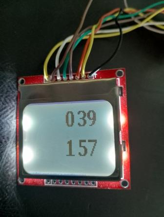
Пример кода с большими цифрами

/*
 * File:   newmain.c
 * Author: User
 *
 * Created on 19 ?????? 2024 ?., 14:20
 */
#include <htc.h>
#pragma config WDTE=OFF, MCLRE=OFF, BOREN=OFF, FOSC=INTRCIO, CP=OFF, CPD=OFF    //,INTRCIO
#define _XTAL_FREQ 4000000

#define LCD_DC  GP0		
#define LCD_RST GP1
#define LCD_DAT GP4
#define LCD_CLK GP5
#define sr GPIO2		//sensor  pin2
#define sr_in TRISIO2=1		//sensor is input
#define sr_out TRISIO2=0		//sensor is output

void writecommand(int command);  // 
void writedata(int data);
void cursorxy (unsigned short x,unsigned short  y);
void clearram(void);
void initlcd(void);
void lcdPrintChar( unsigned short row, unsigned short col,unsigned short ch);

extern const uint8_t SMALL_FONT[];
const uint8_t SMALL_FONT[] = {
   0x00,0xF0,0xFC,0xFE,0x06,0x02,0x06,0xFE,0xFC,0xF0,0x00, // 0
   0x00,0x07,0x1F,0x3F,0x30,0x20,0x30,0x3F,0x1F,0x07,0x00,
   0x00,0x00,0x08,0x0C,0xFC,0xFE,0xFE,0x00,0x00,0x00,0x00, // 1
   0x00,0x20,0x20,0x20,0x3F,0x3F,0x3F,0x20,0x20,0x20,0x00,
   0x00,0x0C,0x0E,0x06,0x02,0x02,0x86,0xFE,0x7C,0x38,0x00, // 2
   0x00,0x30,0x38,0x3C,0x36,0x33,0x31,0x30,0x30,0x38,0x00,
   0x00,0x0C,0x0E,0x86,0x82,0x82,0xC6,0xFE,0x7C,0x38,0x00, // 3
   0x00,0x18,0x38,0x30,0x20,0x20,0x31,0x3F,0x1F,0x0E,0x00,
   0x00,0x00,0xC0,0x20,0x18,0x04,0xFE,0xFE,0xFE,0x00,0x00, // 4
   0x00,0x03,0x02,0x02,0x02,0x22,0x3F,0x3F,0x3F,0x22,0x02,
   0x00,0x00,0x7E,0x7E,0x46,0x46,0xC6,0xC6,0x86,0x00,0x00, // 5
   0x00,0x18,0x38,0x30,0x20,0x20,0x30,0x3F,0x1F,0x0F,0x00,
   0x00,0xC0,0xF0,0xF8,0xFC,0x4C,0xC6,0xC2,0x82,0x00,0x00, // 6
   0x00,0x0F,0x1F,0x3F,0x30,0x20,0x30,0x3F,0x1F,0x0F,0x00,
   0x00,0x06,0x06,0x06,0x06,0x06,0xC6,0xF6,0x3E,0x0E,0x00, // 7
   0x00,0x00,0x00,0x30,0x3C,0x0F,0x03,0x00,0x00,0x00,0x00,
   0x00,0x38,0x7C,0xFE,0xC6,0x82,0xC6,0xFE,0x7C,0x38,0x00, // 8
   0x00,0x0E,0x1F,0x3F,0x31,0x20,0x31,0x3F,0x1F,0x0E,0x00,
   0x00,0x78,0xFC,0xFE,0x86,0x02,0x86,0xFE,0xFC,0xF8,0x00, // 9
   0x00,0x00,0x00,0x21,0x21,0x31,0x1D,0x1F,0x0F,0x03,0x00,
   0xF0,0xF8,0x0C,0x06,0x02,0x02,0x02,0x02,0x0E,0x0C,0x00, // C
   0x03,0x07,0x0C,0x18,0x10,0x10,0x10,0x10,0x1C,0x0C,0x00,
   0x00,0x06,0x06,0x09,0x09,0x09,0x09,0x06,0x06,0x00,0x00, // degrees
   0x00,0x00,0x00,0x00,0x00,0x00,0x00,0x00,0x00,0x00,0x00, 
   0x00,0x80,0x80,0x80,0x80,0x80,0x80,0x80,0x80,0x80,0x00, // minus sign
   0x00,0x01,0x01,0x01,0x01,0x01,0x01,0x01,0x01,0x01,0x00 
  };

unsigned char i;
void main()
 {
 
 GPIO = 0; 
  TRISIO = 0b001100; // 
    ANSEL  = 0x00;       		// Set ports as digital I/O, not analog input
	ADCON0 = 0x00;		 		// Shut off the A/D Converter
	CMCON  = 0x07;		 		// Shut off the Comparator
	VRCON  = 0x00;	    		// Shut off the Voltage Reference

 initlcd();
 clearram();
         //read sensor
     
       
// cursorxy (0,3);	// set the cursor to position x=3 and y-3
 //writedata(255);	// write a solid byte of all 8 bits
 
 while(1){
 
      
              lcdPrintChar(0, 40,0);
            //  lcdPrintChar(3, 47,d[1]);
              lcdPrintChar(0, 53,3);
             // lcdPrintChar(3, 56,d[2]);
              lcdPrintChar(0, 63, 9);
             // lcdPrintChar(3, 70, 11);
               
              lcdPrintChar(3, 40,1);
            //  lcdPrintChar(3, 47,d[1]);
              lcdPrintChar(3, 53,5);
             // lcdPrintChar(3, 56,d[2]);
              lcdPrintChar(3, 63, 7);
             // lcdPrintChar(3, 70, 11);
               
              __delay_ms(1000);
 
 }
 }

void writecommand(int command)
{
LCD_DC=0;                          // byte is a command it is read with the eight SCLK pulse
for (unsigned short t=8;t>0;t--)
   {
   LCD_CLK=0;
   if ((command&0x80)==0)
      {
      LCD_DAT=0;
      }
   else
      {
      LCD_DAT=1;
      }
   LCD_CLK=1;
   command=command<<1;
   }
}

void writedata(int data)
{
LCD_DC=1;
for (unsigned short t=8;t>0;t--)
   {
   LCD_CLK=0;
   if ((data&0x80)==0)
      {
      LCD_DAT=0;
      }
   else
      {
      LCD_DAT=1;
      }
   LCD_CLK=1;
   data=data<<1;
   }
}

void cursorxy (unsigned short x, unsigned short y)          // Nokia LCD Position cursor
{
writecommand(0x40|(y&0x07));
writecommand(0x80|(x&0x7f));
}

void clearram(void)
 {
 unsigned int lcdram;

 cursorxy(0,0);
 for (lcdram=504;lcdram>0;lcdram--)
   writedata(0);                          // write all 504 LCDRAM addresses.
 }

void initlcd(void)
 {
 LCD_RST=0; // reset LCD
 __delay_ms(100);        // Wait 100ms
 LCD_RST=1;// release from reset

 writecommand(0x21);		// Activate Chip and H=1.
 writecommand(0xC2);		// Set LCD Voltage to about 7V.
 writecommand(0x13);		// Adjust voltage bias.
 writecommand(0x20);		// Horizontal addressing and H=0.
 writecommand(0x09);		// Activate all segments.
 clearram();			   // Erase all pixel on the lcdram.
 writecommand(0x08);		// Blank the Display.
 writecommand(0x0C);		// Display Normal.
 cursorxy(0,0);		   // Cursor Home.
 }
void lcdPrintChar( unsigned short row, unsigned short col,unsigned short ch){
    //const unsigned char *chdata = SMALL_FONT + (ch * 22); 
  cursorxy (col,row);
   for(unsigned char i = 0; i < 11; i++) {
   writedata(SMALL_FONT[(ch*22+i)]);}
   cursorxy (col,row+1);
   for(unsigned char i = 11; i < 22; i++) {
   writedata(SMALL_FONT[(ch*22+i)]);}
 writedata(0x00);  
}
http://forum.rcl-radio.ru/uploads/images/2024/06/89b52af8719081a8f8b5054924ec56bd.jpg