Тема: DAC CS8416 + AD1852 — 24bit 192kHz (Arduino)
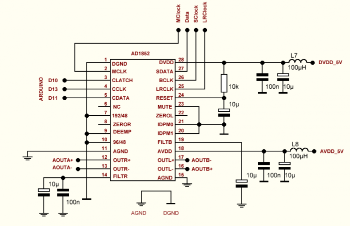
Основная статья - http://rcl-radio.ru/?p=86998
#include <SPI.h>
#include <EEPROM.h>
#include <MsTimer2.h>                    // http://rcl-radio.ru/wp-content/uploads/2018/11/MsTimer2.zip
#include <Encoder.h>                     // http://rcl-radio.ru/wp-content/uploads/2019/05/Encoder.zip
#include <STM32_TM1637.h>                // http://rcl-radio.ru/wp-content/uploads/2020/02/STM32_TM1637_V1_3.zip
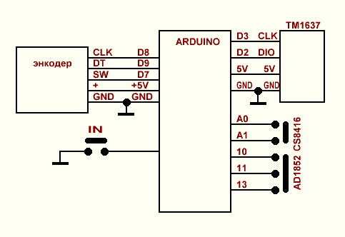
 Encoder myEnc(8, 9);//CLK, DT
 STM32_TM1637 tm(3,2);// CLK, DIO

//  AD1852 SPI
// SS    10 // CLATCH
// MOSI  11 // CDATA
// SCK   13 // CCLK

unsigned long times,oldPosition  = -999,newPosition;
int w,vol,mute,code_mute,in;

void setup(){
 Serial.begin(9600);tm.brig(7); // ЯРКОСТЬ 0...7
 MsTimer2::set(1, to_Timer);MsTimer2::start();
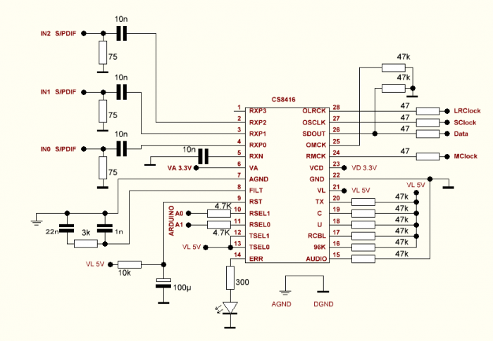
 pinMode(A0,OUTPUT);  // RSEL1 CS8416
 pinMode(A1,OUTPUT);  // RSEL0 CS8416
 pinMode(7,INPUT); // кнопка SW энкодера
 pinMode(6,INPUT_PULLUP); // кнопка IN
 vol = EEPROM.read(0);in = EEPROM.read(1);
 switch(in){
 case 0: digitalWrite(A0, LOW);digitalWrite(A1, LOW);tm.print_float(1,0 ,0b00000100,0b01010100,0,0);break;// px0
 case 1: digitalWrite(A0, LOW);digitalWrite(A1, HIGH);tm.print_float(2,0 ,0b00000100,0b01010100,0,0);break;// px1
 case 2: digitalWrite(A0, HIGH);digitalWrite(A1, LOW);tm.print_float(3,0 ,0b00000100,0b01010100,0,0);break;// px2
 }
 }// setup

void loop(){
   if(digitalRead(7)==LOW&&mute==0){mute=1;code_mute = 0b1000000;tm.print_float(vol,0 ,0b01000000,0b01000000,0b01000000,0b01000000);delay(200);}
   if(digitalRead(7)==LOW&&mute==1){mute=0;code_mute = 0;tm.print_float(vol,0 ,0,0,0,0);delay(200);}

   if(digitalRead(6)==LOW){in++;if(in>2){in=0;}times=millis();w=1;
 switch(in){
 case 0: digitalWrite(A0, LOW);digitalWrite(A1, LOW);tm.print_float(1,0 ,0b00000100,0b01010100,0,0);break;// px0
 case 1: digitalWrite(A0, LOW);digitalWrite(A1, HIGH);tm.print_float(2,0 ,0b00000100,0b01010100,0,0);break;// px1
 case 2: digitalWrite(A0, HIGH);digitalWrite(A1, LOW);tm.print_float(3,0 ,0b00000100,0b01010100,0,0);break;// px2
 }
 delay(2000);tm.print_float(vol,0 ,0,0,0,0);}

   if (newPosition != oldPosition){oldPosition = newPosition;
     vol=vol+newPosition;myEnc.write(0);newPosition=0;w=1;times=millis();
     if(vol>127){vol=127;}if(vol<0){vol=0;}
     Serial.println(vol);
     if(mute==0){tm.print_float(vol,0 ,0,0,0,0);}
     mute=0;code_mute = 0;
     }

   SPI.begin();
   WriteAD1852(0b100010010001+code_mute);  // register control
   WriteAD1852(0b00+(vol<<9)); // register volume left
   WriteAD1852(0b10+(vol<<9)); // register volume right
   delay(10);

   if(millis()-times>5000 && w==1){w=0;EEPROM.write(0,vol);EEPROM.write(1,in);}
  }// loop

 void WriteAD1852(uint16_t Data){
  SPI.beginTransaction(SPISettings(SPI_CLOCK_DIV2, MSBFIRST, SPI_MODE3));
  digitalWrite(SS, HIGH);
  delayMicroseconds(1);
  SPI.transfer16(Data);
  digitalWrite(SS, LOW);
  SPI.endTransaction();
}

void to_Timer(){newPosition = myEnc.read()/4;}
SPI

REGISTER ADDRESSES
The lowest two bits of the 16-bit serial control data word are
decoded as the address of the register into which the upper
14 bits are written.

VOLUME LEFT AND VOLUME RIGHT REGISTERS
A write operation to the left or right volume registers activates
the autoramp, clickless volume control feature of the AD1852.
The upper 10 bits of the volume control word increment or
decrement by 1 at a rate equal to the input sample rate.
int vol = 0...127
DATA VOLUME REGISTR 16 bit = 0b00+(vol<<9) = 0b1111111000000010 = 0 дБ
0b0000000000000001 - min. volume
DATA CONTROL REGISTER = 0b100010010001
25 bit / I2S / Reset / no filter 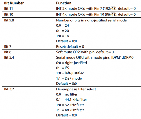
Данный контент доступен только зарегистрированным пользователям.
Данный контент доступен только зарегистрированным пользователям.
Данный контент доступен только зарегистрированным пользователям.