Тема: Анализатор спектра LCD1602
Основная статья - http://rcl-radio.ru/?p=42903
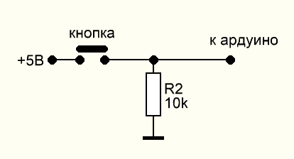
Добавлено 5 режимов отображения полос, управление кнопкой D12 (10 К на GND, управление +5 В). Сигнал подается на вход А0 через разделительный конденсатор 0,1 мкФ.
  #define AUTO_GAIN 1       // автонастройка по громкости
  #define VOL_THR 45        // порог тишины (ниже него отображения на матрице не будет)
  #define LOW_PASS 40       // нижний порог чувствительности шумов (нет скачков при отсутствии звука)
  #define DEF_GAIN 120       // максимальный порог по умолчанию
  #define FHT_N 256         // ширина спектра х2
  #define LOG_OUT 1
  #include <FHT.h>
  #include <EEPROM.h>
  #include <LiquidCrystal.h>
  LiquidCrystal lcd(7, 6, 2, 3, 4, 5);// RS,E,D4,D5,D6,D7
      byte posOffset[16] = {2, 3, 4, 6, 8, 10, 12, 14, 16, 18, 20, 22, 24, 26, 28, 30}; // вч выше
      byte maxValue, maxValue_f,www=1,gain_sp = DEF_GAIN;
      float k = 0.1;
      int i1,yyy,spek;
      unsigned long gainTimer;

  void setup(){
        Serial.begin(9600);
        ADMUX  = 0b01100000; ADCSRA = 0b11010100;
        lcd.begin(16, 2);
        pinMode(12,INPUT);
        spek = EEPROM.read(100);
}

  void loop(){
    if(digitalRead(12)==HIGH){spek++;EEPROM.update(100,spek); www=1;if(spek>5){spek=0;}delay(300);}

      if(spek==0&&www==1){
      byte v1[8] = {0, 0, 0, 0, 0, 0, 0, 4};
      byte v2[8] = {0, 0, 0, 0, 0, 0, 4, 4};
      byte v3[8] = {0, 0, 0, 0, 0, 4, 4, 4};
      byte v4[8] = {0, 0, 0, 0, 4, 4, 4, 4};
      byte v5[8] = {0, 0, 0, 4, 4, 4, 4, 4};
      byte v6[8] = {0, 0, 4, 4, 4, 4, 4, 4};
      byte v7[8] = {0, 4, 4, 4, 4, 4, 4, 4};
      byte v8[8] = {4, 4, 4, 4, 4, 4, 4, 4};
      lcd.createChar(0, v1);lcd.createChar(1, v2);lcd.createChar(2, v3);lcd.createChar(3, v4);lcd.createChar(4, v5);lcd.createChar(5, v6);lcd.createChar(6, v7);lcd.createChar(7, v8);
      www=0;}

      if(spek==1&&www==1){
      byte v1[8] = {0, 0, 0, 0, 0, 0, 0, 14};
      byte v2[8] = {0, 0, 0, 0, 0, 0, 14, 14};
      byte v3[8] = {0, 0, 0, 0, 0, 14, 14, 14};
      byte v4[8] = {0, 0, 0, 0, 14, 14, 14, 14};
      byte v5[8] = {0, 0, 0, 14, 14, 14, 14, 14};
      byte v6[8] = {0, 0, 14, 14, 14, 14, 14, 14};
      byte v7[8] = {0, 14, 14, 14, 14, 14, 14, 14};
      byte v8[8] = {14, 14, 14, 14, 14, 14, 14, 14};
      lcd.createChar(0, v1);lcd.createChar(1, v2);lcd.createChar(2, v3);lcd.createChar(3, v4);lcd.createChar(4, v5);lcd.createChar(5, v6);lcd.createChar(6, v7);lcd.createChar(7, v8);
      www=0;}

      if(spek==2&&www==1){
      byte v1[8] = {0, 0, 0, 0, 0, 0, 0, 10};
      byte v2[8] = {0, 0, 0, 0, 0, 0, 10, 10};
      byte v3[8] = {0, 0, 0, 0, 0, 10, 10, 10};
      byte v4[8] = {0, 0, 0, 0, 10, 10, 10, 10};
      byte v5[8] = {0, 0, 0, 10, 10, 10, 10, 10};
      byte v6[8] = {0, 0, 10, 10, 10, 10, 10, 10};
      byte v7[8] = {0, 10, 10, 10, 10, 10, 10, 10};
      byte v8[8] = {10, 10, 10, 10, 10, 10, 10, 10};
      lcd.createChar(0, v1);lcd.createChar(1, v2);lcd.createChar(2, v3);lcd.createChar(3, v4);lcd.createChar(4, v5);lcd.createChar(5, v6);lcd.createChar(6, v7);lcd.createChar(7, v8);
      www=0;}

      if(spek==3&&www==1){
      byte v1[8] = {0, 0, 0, 0, 0, 0, 0, 27};
      byte v2[8] = {0, 0, 0, 0, 0, 0, 27, 27};
      byte v3[8] = {0, 0, 0, 0, 0, 27, 27, 27};
      byte v4[8] = {0, 0, 0, 0, 27, 27, 27, 27};
      byte v5[8] = {0, 0, 0, 27, 27, 27, 27, 27};
      byte v6[8] = {0, 0, 27, 27, 27, 27, 27, 27};
      byte v7[8] = {0, 27, 27, 27, 27, 27, 27, 27};
      byte v8[8] = {27, 27, 27, 27, 27, 27, 27, 27};
      lcd.createChar(0, v1);lcd.createChar(1, v2);lcd.createChar(2, v3);lcd.createChar(3, v4);lcd.createChar(4, v5);lcd.createChar(5, v6);lcd.createChar(6, v7);lcd.createChar(7, v8);
      www=0;}

      if(spek==4&&www==1){
      byte v1[8] = {0, 0, 0, 0, 0, 0, 0, 31};
      byte v2[8] = {0, 0, 0, 0, 0, 0, 31, 31};
      byte v3[8] = {0, 0, 0, 0, 0, 31, 31, 31};
      byte v4[8] = {0, 0, 0, 0, 31, 31, 31, 31};
      byte v5[8] = {0, 0, 0, 31, 31, 31, 31, 31};
      byte v6[8] = {0, 0, 31, 31, 31, 31, 31, 31};
      byte v7[8] = {0, 31, 31, 31, 31, 31, 31, 31};
      byte v8[8] = {31, 31, 31, 31, 31, 31, 31, 31};
      lcd.createChar(0, v1);lcd.createChar(1, v2);lcd.createChar(2, v3);lcd.createChar(3, v4);lcd.createChar(4, v5);lcd.createChar(5, v6);lcd.createChar(6, v7);lcd.createChar(7, v8);
      www=0;}

      if(spek==5&&www==1){
      byte v1[8] = {0, 0, 0, 0, 0, 0, 0, 21};
      byte v2[8] = {0, 0, 0, 0, 0, 0, 21, 21};
      byte v3[8] = {0, 0, 0, 0, 0, 21, 21, 21};
      byte v4[8] = {0, 0, 0, 0, 21, 21, 21, 21};
      byte v5[8] = {0, 0, 0, 21, 21, 21, 21, 21};
      byte v6[8] = {0, 0, 21, 21, 21, 21, 21, 21};
      byte v7[8] = {0, 21, 21, 21, 21, 21, 21, 21};
      byte v8[8] = {21, 21, 21, 21, 21, 21, 21, 21};
      lcd.createChar(0, v1);lcd.createChar(1, v2);lcd.createChar(2, v3);lcd.createChar(3, v4);lcd.createChar(4, v5);lcd.createChar(5, v6);lcd.createChar(6, v7);lcd.createChar(7, v8);
      www=0;}

      analyzeAudio();   // функция FHT, забивает массив fht_log_out[] величинами по спектру

      for (int pos = 0; pos < 16; pos++) {
        if (fht_log_out[posOffset[pos]] > maxValue) maxValue = fht_log_out[posOffset[pos]];
        lcd.setCursor(pos, 0);
        int posLevel = map(fht_log_out[posOffset[pos]], LOW_PASS, gain_sp, 0, 15);posLevel = constrain(posLevel, 0, 15);

  while(yyy<2){yyy++;delay(2);
    if (posLevel > 7) {lcd.write((uint8_t)posLevel-8);lcd.setCursor(pos, 1);lcd.write((uint8_t)7);}
     else {lcd.print(" ");lcd.setCursor(pos, 1);lcd.write((uint8_t)posLevel); }}yyy=0;}

   if (AUTO_GAIN) {
    maxValue_f = maxValue * k + maxValue_f * (1 - k);
    if (millis() - gainTimer > 1500) {
    if (maxValue_f > VOL_THR) gain_sp = maxValue_f;
      else gain_sp = 150;gainTimer = millis();}
      else {gain_sp = DEF_GAIN;}}
  }// loop

void analyzeAudio() {
 while(i1 < FHT_N){i1++;
    do{ADCSRA |= (1 << ADSC);}
    while((ADCSRA & (1 << ADIF)) == 0);fht_input[i1] = (ADCL|ADCH << 8);}i1=0;
    fht_window(); // window the data for better frequency response
    fht_reorder(); // reorder the data before doing the fht
    fht_run(); // process the data in the fht
    fht_mag_log(); // take the output of the fht
}

